Last reviewed 30 May 2026
Dynamic Balancing from A to Z: The Complete Guide to Eliminating Vibration and Imbalance
Every year, up to 30% of industrial equipment failures are caused by vibration. In 9 cases out of 10, the root cause is rotor imbalance. It is an invisible enemy that slowly but surely destroys machinery from the inside out: from premature bearing wear through to catastrophic failures and emergency downtime.
Imbalance is not a minor fault but a serious threat to any rotating equipment. Ignoring the problem leads to ruinous consequences: up to 80% of bearing failures are caused by imbalance or misalignment, excess energy consumption can reach 10-25%, and the cost of unplanned emergency downtime runs into hundreds of thousands of pounds.
What you will learn from this guide:
- The physical nature of imbalance and why it occurs
- The types of imbalance and how each is corrected
- When and why balancing is necessary
- Modern balancing methods and equipment
- Balance quality grades and the ISO standards
- The economic case for balancing in good time
- How to order a balancing service correctly
Chapter 1: What is imbalance — the root of the problem?
A simple explanation
Imbalance (or unbalance) is a condition in which the mass of a rotating part is distributed unevenly with respect to the axis of rotation. Put more simply, the rotor's centre of mass does not coincide with its geometric axis.
An everyday analogy: Think of how a washing machine "jumps" during the spin cycle when the laundry bunches up on one side. Or how a car's steering wheel shakes at speed when a wheel has not been balanced after a tyre change. In both cases the culprit is the uneven distribution of mass around the axis of rotation. Exactly the same thing happens in industrial rotors — the metal is heavier in one spot, and as it spins this produces a runout.
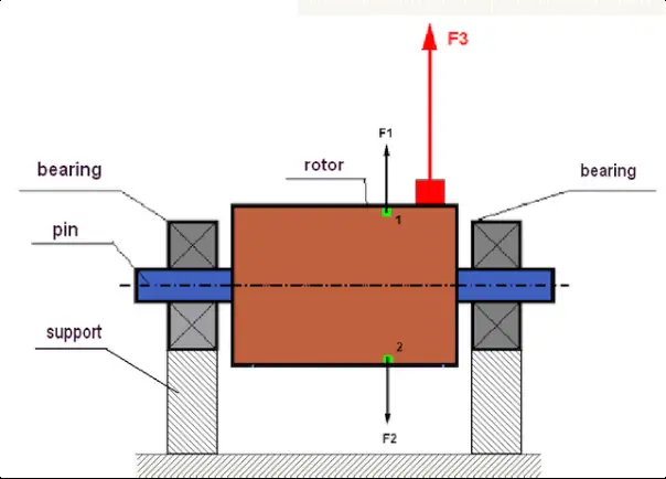
Fig. 1. Rotor and centrifugal forces: in a perfectly balanced rotor the forces F1 and F2 cancel each other out, but an asymmetric mass (red) creates the unbalanced force F3
The force of imbalance in action: An imbalance of just 10 grams on a fan rotor 1 metre in diameter, spinning at 1,500 rpm, generates a cyclic force equivalent to about 12.5 kgf! It is as if a 12.5 kg hammer were striking the bearings 25 times every second.
Ideally, the mass of a rotor should be symmetrical about the axis of rotation. The centrifugal forces that arise as it spins then cancel each other out and there is virtually no vibration. But as soon as even a small asymmetry appears (uneven wear, the build-up of dirt, a manufacturing defect), an unbalanced centrifugal force is produced during rotation, and this causes vibration.
Types of imbalance
Imbalance can take several forms. Three basic types are distinguished:
Static imbalance (single-plane)
This occurs when the rotor's centre of mass is displaced parallel to the axis of rotation. You can picture it as a single "heavy spot" on the rotor. Even at rest, placed on horizontal supports, such a rotor will always roll round so that the heavy side ends up at the bottom.
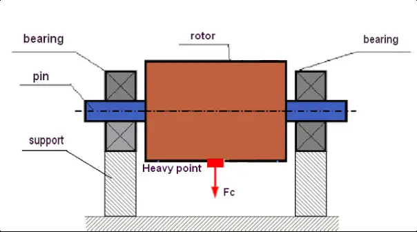
Fig. 2. Static imbalance: the "heavy spot" always rolls to the bottom under the force of gravity
Static imbalance is typical of narrow, disc-shaped rotors (grinding wheels, thin pulleys, narrow fan impellers). It is relatively simple to correct — by fitting a single correction weight in one plane, diametrically opposite the "heavy spot".
Couple (moment) imbalance
A more complex case. It arises when two equal unbalanced masses sit in different planes along the length of the rotor, set 180° apart. At rest such a rotor is balanced — it has no single "heavy spot" and will not roll round on its own.
As it spins, however, these two masses create a couple (a moment) that makes the rotor "rock" or "wobble" vigorously. Correcting couple imbalance requires mass correction in at least two planes.
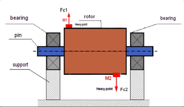
Fig. 3. Dynamic (couple) rotor imbalance: the unequal masses M1 and M2 create a couple of centrifugal forces F1 and F2 that make the rotor "rock"
Dynamic imbalance
This is the most general and, in practice, the most common case. Dynamic imbalance is a combination of static and couple imbalance. It only shows itself during rotation and is the main cause of vibration in most industrial rotors.
Correcting dynamic imbalance always requires mass correction in at least two planes (two-plane balancing). That is why professional dynamic balancing is carried out with specialised instruments capable of measuring vibration at several points simultaneously.
More on the types of imbalance: static, couple and dynamic — what is the difference?
The causes of imbalance
Imbalance can be either "inherent" (manufacturing defects) or "acquired" during service. Understanding the causes helps not only to correct the present imbalance but also to prevent it from returning.
Manufacturing (inherent) defects
These arise at the production stage of a component:
- Inaccuracies in casting or machining: uneven wall thickness, offset bores, turning errors
- Material inhomogeneity: porosity in a casting, inclusions and voids in the metal create an uneven distribution of density
- Assembly errors: when a rotor is built up from several parts (discs, blades, hub), tolerances stack up and produce imbalance
When equipment is commissioned, there is a risk of "inherent" imbalance from factory defects. For this reason, critical equipment (pump and fan rotors, crankshafts) is best balanced before installation or immediately after assembly.
Operational (acquired) defects
These appear during the operation of the equipment and are the most common cause of imbalance:
- Uneven wear: working surfaces wear at different rates — fan blades, crusher hammers, cutter knives. Abrasive wear, erosion and mechanical damage all create asymmetry
- Deformation: a shaft bent by overheating, impact or overload. Loose fixings that let the rotor "wander" and distort in service
- Material build-up: dust, dirt and process material accumulate on fan blades. On crusher rotors, the material being processed sticks on. Even a small, uneven build-up at a large radius creates significant imbalance
- Corrosion: chemical corrosion and droplet erosion from ingressing liquid create pitting and an uneven loss of mass
- Loss of components: the sudden loss of a turbine blade, a gear tooth or a crusher hammer leads to severe, abrupt imbalance
"Acquired" imbalance builds up gradually during service. This makes regular vibration diagnostics and planned balancing work an essential part of maintenance.
Repair-induced defects
These arise after repairs have been carried out:
- Poor-quality assembly: incorrect fitting of parts, failure to follow assembly procedures
- Asymmetric fixings: replacing individual blades, beaters or hammers without rebalancing the whole assembly
- Welding errors: uneven weld build-up, weld beads of differing mass
- Careless fitting: the rotor seated at an angle when fitted to the shaft
Any major intervention in a rotor's construction during repair (replacing parts, welding, turning) carries a high risk of "repair-induced" imbalance and calls for mandatory rebalancing afterwards.
The consequences of ignoring imbalance
Ignoring even a small imbalance leads to a cascade of destructive consequences:
The dangers of imbalance:
- Accelerated bearing wear: up to 80% of bearing failures are caused by balancing or alignment problems. Service life can fall from several years to a few months
- Cracks in the structure: constant vibration causes metal fatigue, leading to cracks in the frame and foundation and to fixing bolts working loose
- Excess energy consumption of 10-25%: a considerable share of the energy is not spent on useful work but on "shaking" the machine
- Reduced product quality: vibration has a negative impact on the manufacturing process
- Emergency downtime: imbalance ultimately leads to sudden failure and the shutdown of an entire production line
- Safety hazards: increased noise, operator fatigue and the risk of rotating parts breaking free
How to identify the cause of vibration: a guide to vibration diagnostics
Chapter 2: Dynamic balancing — the modern solution
Dynamic balancing is the process of removing the imbalance of a rotating part, carried out with the rotor running (in its working mode). Unlike static balancing, which is done without rotation, dynamic balancing makes it possible to correct both static imbalance (a displaced centre of mass) and couple imbalance (an uneven distribution of mass along the length of the rotor).
How it works: 5 steps
Professional dynamic balancing is carried out in several stages:
- Measuring vibration: highly sensitive sensors (accelerometers) measure the amplitude and phase of vibration at the bearing supports
- Locating the "heavy spot": a specialised instrument (a vibration analyser-balancer) analyses the signal and determines exactly where the unbalanced mass sits on the rotor
- Calculating the correction weights: from the data obtained, the precise mass and angular position of the correction weight (or several weights, for two-plane balancing) is calculated automatically
- Fitting/removing weights: correction weights are fixed to the rotor (by welding or with screws), or conversely excess mass is removed (by drilling)
- Verification check: after the weights are fitted, vibration is measured again to confirm that the level has been reduced to within permissible limits
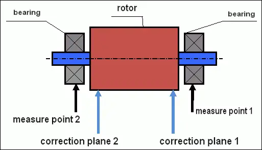
Fig. 4. Dynamic balancing diagram: vibration sensors are mounted on the supports at points 1 and 2, and correction weights are fitted in the two correction planes
Vibration diagnostics and balancing services
We carry out vibration diagnostics and identify the causes of elevated vibration in your equipment
Get in touchChapter 3: Which equipment needs balancing?
Almost any rotating component may require balancing. Here are the main objects that specialists work with:
3.1. Fans and flue-gas fans
Industrial fans are especially prone to imbalance. During operation, dust, dirt and process material build up on the blades of the impeller, shifting the centre of mass. Uneven blade wear, distortion and corrosion are also possible.
After an induced-draught fan at one precast-concrete plant was balanced, an annual electricity saving worth around €8,050 was achieved and bearing life increased from 4 months to 2 years.
More detail: 5 causes of industrial fan vibration and how to eliminate them
3.2. Electric motors and generators
Electric-motor rotors and generator armatures are among the most common objects for balancing. After a motor winding is rewound, balancing the rotor is mandatory, because rewinding can alter the distribution of mass. Even a small imbalance at high speed (3,000 rpm) generates significant vibration forces.
Particular points when balancing electric motors:
- The armature is often balanced as an assembly with the commutator
- The required balance quality grade is usually G2.5 - G6.3
- After rewinding, both mechanical and magnetic imbalance are possible
- Workshop balancing is preferred for accuracy
More detail: balancing an electric-motor armature after rewinding and repair
3.3. Pumps and compressors
Pump impellers, turbine rotors and compressor impellers are business-critical equipment for many industries. Imbalance in a pump impeller creates not only vibration but other problems too:
- Premature failure of mechanical seals: vibration causes shaft runout, which destroys the seal and leads to leaks
- Cavitation: unstable running caused by vibration can worsen cavitation effects
- Increased bearing wear: especially critical for high-pressure pumps
When an industrial pump is repaired, every impeller must be balanced — in the workshop (if removed) or on site (once assembled). A combined approach is often used: the impeller is first balanced on its own, then the fully assembled pump rotor is rebalanced in its assembled state.
More detail: balancing pumps and extending seal life
3.4. Agricultural machinery
Combine threshing drums, straw-chopper rotors, flails, mulcher shafts and rotary mowers. In agriculture, a machine breaking down in the middle of sowing or harvesting means not just downtime but direct losses from a lost crop.
More detail: balancing agricultural machinery for reliability through the season
Chapter 4: Two main approaches: in the workshop or on site?
There are two basic ways of carrying out balancing work, each with its own advantages and field of application.
Workshop balancing (on a machine)
The rotor (or shaft, or wheel) is removed from the machine and mounted on a dedicated balancing machine. The machine spins the rotor up to the required speed and measures the imbalance. Modern balancing machines are computer-controlled — they calculate the magnitude and angular position of the weights needed to remove the imbalance.
Advantages: high balancing accuracy for an individual component, the ability to carry out accompanying repair work (turning, welding), and controlled workshop conditions.
Disadvantages: it requires complete dismantling, transport and subsequent reassembly of the component, which considerably increases equipment downtime. It also does not account for the influence of coupled systems: supports, bearings and the foundation.
In-situ balancing (on site)
Balancing is carried out directly on the customer's equipment, in its own bearings, without removing the rotor. Using a portable vibration measurement system and a laser tachometer, the engineer balances the unit at its working speed, right where it is installed.
Advantages: minimal downtime (the work often takes just a few hours) and substantial savings on dismantling and reassembly. The main advantage is that the whole system is balanced as an assembly, taking real operating conditions into account.
Disadvantages: access to the rotor is needed to fit correction weights, and it must be possible to start and stop the unit several times.
A detailed comparison: in-situ balancing vs. workshop balancing — which to choose?
Chapter 5: Balance quality grades and ISO standards
The quality of balancing is assessed against international standards. The key document is ISO 21940-11 (formerly ISO 1940-1), which defines the balance quality grades (denoted by the letter G).
What is a G grade?
The grade defines the permissible residual imbalance after balancing. The lower the G number, the stricter the accuracy requirement. Each type of equipment has its own recommended grade:
| G grade | Type of equipment | Examples |
|---|---|---|
| G16 | Coarse balancing | Crushers, agricultural machinery, drive shafts |
| G6.3 | Standard industrial quality | Fans, pumps, electric motors |
| G2.5 | Higher quality | Turbines, compressors, machine-tool drives |
| G1.0 | Precision balancing | Machine-tool spindles |
| G0.4 | Ultra-precision balancing | Precision grinding-machine spindles |
A detailed guide: balance quality grades under ISO 21940-11 with calculation formulae
Chapter 6: Why balancing is an investment, not a cost
The cost of balancing a rotor or shaft is incomparably lower than the cost of the downtime and repairs incurred when equipment is taken out of service by vibration. By balancing machinery in good time, you save on bearing replacement, casing repairs and unplanned production stoppages.
Direct savings from balancing:
- Bearing costs reduced by 70-80%: timely balancing extends bearing life several times over
- Energy savings of 10-25%: balanced equipment consumes less energy because it does not waste power on vibration
- Prevention of costly downtime: an emergency stoppage of a production line can cost hundreds of thousands of pounds a day
- Equipment life increased by 2-3×: no vibration means no fatigue damage to the metal
Case study: a precast-concrete plant
Equipment: the induced-draught fan of a boiler unit
Problem: elevated vibration, with bearings being replaced every 4 months
Solution: dynamic balancing of the impeller on site
Result:
- Electricity saving: around €8,050/year
- Bearing life: up from 4 months to 2 years
- ROI (payback): 1.5 months
The full calculation: the economic effect of balancing with real-world cases
A professional balancing centre: what matters
Balancing is not merely a technical procedure but responsible work that demands skill and experience. By entrusting it to professionals, you gain a guarantee of a quality result.
Specialists' recommendations on balancing
Following these recommendations will help you get the maximum benefit from balancing and extend the working life of your equipment.
Frequently asked questions
When do rotors need balancing?
Balancing is required whenever vibration levels rise, after any repair to rotating parts, after replacing rotor components, and also routinely as part of planned maintenance (typically once every 1-2 years for business-critical equipment).
Can equipment be balanced without dismantling it?
Yes. This is known as in-situ or field balancing. Using portable instruments, a specialist can balance the rotor right where it is installed, without removing it from the machine. This approach saves both time and the cost of dismantling.
How much does balancing cost?
The price depends on the weight of the rotor, the complexity of the equipment and the balancing method. As a rough guide: small rotors (up to 100 kg) — from EUR 150-250, medium (100-1000 kg) — from EUR 250-500, large (over 1000 kg) — from EUR 500.
Balancing and vibration diagnostics
Instruments for doing the job yourself and the services of our specialists
The Balanset-1A instrument
A universal balancing instrument for all types of rotor
Buy the instrument