Last reviewed 30 May 2026
How to dynamically balance a rotor in its own bearings with the Balanset-1A
This is a detailed technical guide written for engineers and maintenance specialists who plan to carry out rotor balancing themselves using the portable Balanset-1A instrument.
Who this guide is for:
- Chief mechanic's department engineers
- Repair-department specialists
- Service engineers
- Technical specialists with a basic grounding in vibration diagnostics
What you will learn: The complete balancing procedure from preparation through to quality control, including sensor mounting, the 3-run method, correction weight calculation and common mistakes.
Stage 1: Preparing for balancing
The foundation of success: Thoroughly cleaning the rotor, checking the condition of the bearings and foundation, and carrying out preliminary vibration diagnostics to rule out other defects are mandatory prerequisites for successful balancing. Preparation determines 80% of the result.
Initial vibration diagnostics (is it really imbalance?)
Before balancing, always take a preliminary measurement in Vibrometer mode (F5):
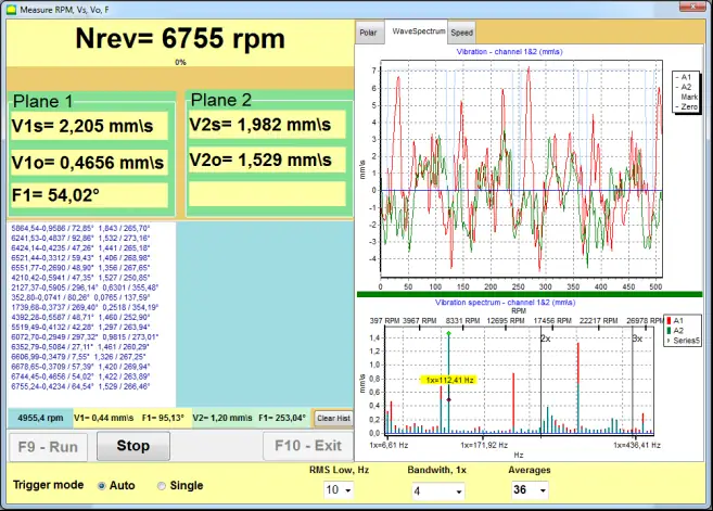
Fig. 1. The key check: compare the overall vibration (V1s, V2s) with the vibration at the rotational frequency (V1o, V2o)
Diagnostic rule:
- If V1s ≈ V1o → the dominant source of vibration is rotor imbalance, and balancing will be effective
- If V1s ≫ V1o → a significant part of the vibration is caused by other sources (misalignment, bearings, looseness). Balancing alone will not solve the problem
Mechanical inspection (checklist)
Rotor:
- Thoroughly clean every surface, removing dirt, rust and any built-up product
- Check that no components are broken or missing (blades, hammers)
- Make sure there are no loose parts
Bearings:
- Check for excessive play, unusual noises and overheating
- Worn bearings with a lot of play make it impossible to obtain stable readings
Foundation and frame:
- Make sure the unit is mounted on a rigid foundation
- Check that the anchor bolts are tight and there are no cracks
- Eliminate any "soft foot" (where one support does not sit flush against the foundation)
Stage 2: Setting up the Balanset-1A
Mounting the vibration sensors
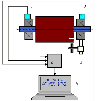
Fig. 2. Sensor mounting layout: 1, 2 — vibration sensors on the bearings, 3 — laser tachometer, 4 — USB unit, 5 — laptop
Where to mount them:
- On the bearing housings, as close to the bearing as possible
- For the strongest signal — in the direction of maximum vibration (usually horizontal)
Stage 3: Run 0 — initial measurement
Aim: to measure the original vibration level without fitting any weights.
Procedure:
- Start the machine and bring it up to a stable operating speed
- Make sure the rotational speed is steady (not fluctuating)
- In the software, press the "Run #0" button
- The instrument records the rotational speed, vibration amplitude and phase
Stages 4–5: Run 1 and Run 2 — trial weights
Aim: to establish how the system responds to a known change in mass.
Choosing the trial weight mass
The trial weight must produce a noticeable change in the vibration:
- A 20–30% change in amplitude, OR
- A 20–30° change in phase
Stage 6: Calculating and fitting the correction weights
Based on the vector changes recorded during the trial runs, the software automatically calculates the mass and fitting angle of the correction weight for each plane.
Fixing methods:
- Welding: small metal plates are welded on (the most reliable and durable method)
- Bolted connection: where threaded holes already exist or can be drilled
- Special clamps: for certain types of rotor
- Removing mass: drilling out holes (less preferred)
Stage 7: Run 3 — verification measurement
After fitting the permanent correction weights:
- Start the machine
- Press "RunTrim"
- The software measures the residual vibration
- Compare it against the tolerance to ISO 1940
Success criteria:
- The vibration has been reduced by a factor of 5–10
- The residual imbalance is within tolerance
- Vibration falls in zone A or B to ISO 20816
Stage 8: Common mistakes and how to avoid them
Mistake 1: balancing a dirty or faulty rotor
The problem: Trying to balance a rotor that has caked-on dirt, worn bearings or play.
The fix: Always check the condition of the machine before balancing. Cleaning and repair come first.
Mistake 2: trial weight too small
The problem: The trial weight is too light and the vibration changes by less than 20%.
The fix: Increase the trial weight by a factor of 1.5–2 and repeat Run 1.
Mistake 3: unstable rotational speed
The problem: The speed "wanders" between runs, or the machine is running close to resonance.
The fix: Fix the speed (e.g. 1500 rpm for all measurements). If the phase "jumps", change the speed by ±10–15% to move out of the resonance zone.
Conclusion
The Balanset-1A balancing method, based on the influence-coefficient (3-run) method, lets you carry out high-quality rotor balancing directly at the point of installation.
The key principles for success:
- Careful preparation (80% of success)
- Choosing the right trial weight mass (a 20–30% change in vibration)
- A stable rotational speed across all runs
- Following the method precisely
- Verification against ISO standards
When the method is followed, balancing usually succeeds at the first attempt. If the result is unsatisfactory, go back to the diagnostics: the problem may not be imbalance at all, but misalignment, bearings or resonance.
Balancing with the Balanset-1A
Instruments for doing the work yourself and on-site balancing services
The Balanset-1A instrument
A portable balancing instrument with vibration-diagnostics functionality
Buy the instrumentQuick checklist
- Take a preliminary Vibrometer-mode measurement first
- Clean the rotor and check bearings, foundation, soft foot
- Mount sensors on bearing housings near the bearing
- Run 0, then trial weights in planes 1 and 2
- Pick a trial weight giving 20-30% amplitude or phase change
- Fit calculated correction weights and verify with Run 3