Last reviewed 30 May 2026
Balance Quality Grades under ISO 21940-11: How to Choose the Right Tolerance for Your Equipment
The quality of balancing should be assessed not subjectively ("the vibration has gone down") but against objective, measurable criteria. International standards set out clear requirements for the permissible residual imbalance after balancing.
The key document is ISO 21940-11 (formerly ISO 1940-1:2007), "Mechanical vibration — Rotor balancing — Procedures and tolerances for rotors with rigid behaviour".
Why standards are needed:
- They turn a subjective judgement into an objective, measurable criterion
- They serve as the basis for the customer's acceptance of the work
- They strike the balance between technical necessity and economic sense
- They protect both the contractor and the customer in the event of a dispute
What a G grade is, in plain language
The balance quality grade (denoted by the letter G) defines the permissible residual imbalance after balancing. The lower the G number, the stricter the balancing accuracy requirement.
Physical meaning: the G number equals the orbital velocity of the rotor's centre of mass at its service speed — the product of the permissible specific unbalance and the angular speed (eper × Ω), expressed in mm/s. For example, grade G6.3 corresponds to 6.3 mm/s.
Important: this is a property of the residual unbalance, not the casing or bearing-housing vibration velocity that is measured on a running machine to ISO 20816-3. The two are related but are not the same number.
An important principle: each type of equipment has its own recommended balance quality grade, which stays constant regardless of the rotational speed or the mass of the rotor. For example:
- Crushers → always grade G16
- Fans and pumps → always G6.3
- Turbines → always G2.5
- Spindles → always G1.0 or G0.4
A table of G balance quality grades for different equipment
| G grade | Permissible vibration velocity (mm/s) | Type of equipment | Rotor examples |
|---|---|---|---|
| G4000 | 4000 | Very coarse balancing | Rigidly mounted crankshafts of slow-running marine diesels (with an odd number of cylinders) |
| G16 | 16 | Coarse balancing | Crushers, agricultural-machinery shafts, drive (cardan) shafts |
| G6.3 | 6.3 | Standard industrial quality | Pump rotors, fan impellers, electric-motor armatures, process-equipment components |
| G2.5 | 2.5 | Higher quality | Gas- and steam-turbine rotors, turbocompressors, machine-tool drives, special-purpose electric-motor armatures |
| G1.0 | 1.0 | Precision balancing | Grinding-machine drives, spindles |
| G0.4 | 0.4 | Ultra-precision balancing | Precision grinding-machine spindles, gyroscopes |
← See also the section on balance quality grades in the complete guide
How to calculate the permissible residual imbalance
ISO 21940-11 lets you calculate a specific value for the permissible residual imbalance, which serves as the target figure during balancing.
The calculation is done in two stages:
Stage 1: Determining the permissible specific imbalance (eper)
Formula:
eper = (G × 9549) / n
Where:
- G — the balance quality grade (for example, 6.3)
- n — the working rotational speed, rpm
- eper — the permissible specific imbalance, μm (or g·mm/kg)
Stage 2: Calculating the permissible residual imbalance (Uper)
Formula:
Uper = eper × M
Where:
- M — the mass of the rotor, kg
- Uper — the permissible residual imbalance, g·mm
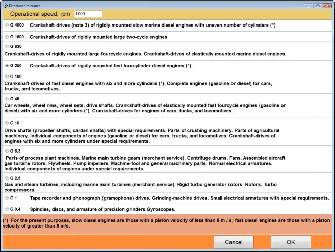
Fig. 1. The balancing tolerance calculation window in the Balanset-1A software: automatic calculation to ISO 1940-1
Balancing with verification against the standards
We carry out balancing with the tolerance calculated to ISO 21940-11 and issue a certificate of conformity
Order the serviceWorked examples
Example 1: an industrial fan
Input data:
- Mass of the rotor (impeller + shaft): M = 150 kg
- Working speed: n = 1500 rpm
- Balance quality grade: G = 6.3 (standard for fans)
Calculation:
- eper = (6.3 × 9549) / 1500 = 40.1 μm (g·mm/kg)
- Uper = 40.1 × 150 = 6015 g·mm
Conclusion: after balancing, the residual imbalance must not exceed 6015 g·mm (or ~6000 g·mm rounded).
Example 2: a 30 kW electric-motor rotor
Input data:
- Mass of the rotor: M = 25 kg
- Working speed: n = 3000 rpm
- Balance quality grade: G = 2.5 (higher quality)
Calculation:
- eper = (2.5 × 9549) / 3000 = 7.96 μm
- Uper = 7.96 × 25 = 199 g·mm
Conclusion: the motor requires more accurate balancing (grade G2.5 rather than G6.3) because it runs at high speed.
Example 3: a grinding-machine spindle
Input data:
- Mass of the spindle with its tool: M = 5 kg
- Working speed: n = 6000 rpm
- Balance quality grade: G = 1.0 (precision balancing)
Calculation:
- eper = (1.0 × 9549) / 6000 = 1.59 μm
- Uper = 1.59 × 5 = 7.95 g·mm
Conclusion: for high-speed precision spindles the requirements are very strict — the permissible specific imbalance (eper) is about 25 times smaller than for fans.
Practical application: if the final balancing report shows that the residual imbalance is within the calculated ISO tolerance, the work is deemed to have been carried out to a high standard. This is an objective, legally meaningful criterion.
The link to equipment vibration
In addition to ISO 21940-11 (the imbalance tolerance), there is ISO 20816-3:2022 — which superseded the now-withdrawn ISO 10816-3 — governing the permissible vibration levels of equipment measured on the bearing housings. It classifies machines into groups and 2 foundation types (rigid/flexible).
| Machine group | Power (P), kW | Zone boundaries (mm/s) | ||
|---|---|---|---|---|
| A/B Good |
B/C Acceptable |
C/D Alarm |
||
| Group 1 (Large machines) |
P > 300 kW | 2.3 | 4.5 | 7.1 |
| Group 2 (Medium machines) |
15 kW < P ≤ 300 kW | 1.4 | 2.8 | 4.5 |
Note: data for machines on rigid foundations.
Decoding the condition zones:
Zone A: Good
The condition of new equipment. No action is needed.
Zone B: Acceptable
Unrestricted operation is permitted. Monitoring is recommended.
Zone C: Temporarily acceptable
The equipment needs diagnostics to find and eliminate the causes of vibration.
Zone D: Unacceptable (Alarm)
The vibration may cause damage. An immediate stop and repair are required.
Critical vibration levels:
- Above 7 mm/s is already considered dangerous under ISO — the unit should be stopped for diagnostics to prevent destruction of the bearings and casing
- Above 10 mm/s can lead to fatigue cracking of casing welds and rapid failure of components. This is the critical zone!
The two standards complement each other: ISO 21940-11 defines the target balancing quality, while ISO 20816-3 assesses the machine's actual vibration condition.
Conclusion
ISO 21940-11 is not merely a formal requirement but a practical tool for assuring balancing quality. It lets you:
- Objectively assess the quality of the work carried out
- Choose an economically justified level of accuracy
- Protect the interests of both the customer and the contractor
- Provide documented proof of quality
Modern balancing instruments such as the Balanset-1A have a built-in tolerance calculator to ISO 1940-1 that automatically computes the target values and compares the results achieved against them.
Balancing to ISO standards
Instruments and services with tolerances calculated to the standards
Balancing services
Balancing with calculations to ISO and a certificate of conformity
Order the serviceQuick checklist
- Pick the G grade for your equipment type
- Record rotor working speed (rpm) and mass
- Compute e_per = (G x 9549) / n
- Compute U_per = e_per x M
- Confirm residual imbalance is within the tolerance
- Issue a certificate of conformity