Last reviewed 30 May 2026
Types of Imbalance: Static, Couple and Dynamic — What Is the Difference?
Understanding the type of imbalance is critical to balancing correctly. It determines how many correction planes you will need (one or two), which balancing method to choose and what result you can expect.
Trying to correct dynamic imbalance using single-plane balancing methods is a common mistake that leads to wasted time and unsatisfactory results. In this article we look in detail at each type of imbalance, learn to tell them apart and identify the optimal strategy for correcting them.
In this article you will learn:
- The physical nature of each type of imbalance
- How to identify the type of imbalance from the rotor's geometry
- How many correction planes are needed
- Practical examples for different equipment
Static imbalance (single-plane)
The physics
Static imbalance occurs when the rotor's principal central axis of inertia is displaced parallel to the axis of rotation. Put more simply, there is a single "heavy spot" on the rotor that shifts the centre of mass.
Force calculation: A rotor imbalance of 1 gram at a radius of 100 mm, running at 3,000 rpm, creates a centrifugal force of almost 10 N — the equivalent of a hammer blow 50 times a second. Even a small imbalance places a colossal cyclic load on the bearings.
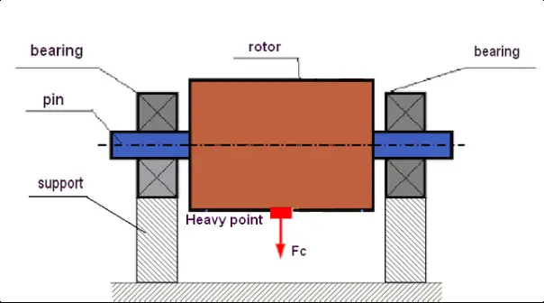
Fig. 1. Static imbalance: the heavy spot always rolls to the bottom under the force of gravity. At rest, the rotor settles into a definite position.
How it shows itself
The unique feature of static imbalance is that it is apparent even at rest. If such a rotor is placed on horizontal knife-edges, or suspended on an axis with minimal friction, gravity will always turn it so that it comes to rest with the "heavy spot" at the bottom.
This is precisely the principle behind simple static balancing "on knife-edges" — a method known since the 19th century.
Which rotors it is typical of
Static imbalance dominates in narrow, disc-shaped rotors where the length-to-diameter ratio (L/D) is small — less than 0.25-0.5. Examples:
- Grinding wheels
- Thin pulleys
- Narrow fan impellers
- Circular saws
- Thin flywheels
The correction method
It is corrected by fitting a single correction weight in one correction plane, diametrically opposite the "heavy spot" (180° away).
It can even be done without rotating the rotor — by static balancing on knife-edges. For an accurate result, however, dynamic balancing with vibration measurement at the working speed is recommended.
Couple (moment) imbalance
The physics
Couple imbalance arises when the rotor's principal axis of inertia intersects the axis of rotation at the centre of mass but is set at an angle to it. Physically, this corresponds to two equal unbalanced masses placed in different planes along the rotor and set 180° apart around the circumference.
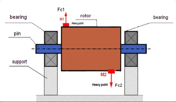
Fig. 2. Couple imbalance: the two masses M1 and M2 create a couple of centrifugal forces F1 and F2 that make the rotor "rock" or "wobble"
How it shows itself
At rest (without rotation) such a rotor is balanced — it will not try to settle into any particular position on the knife-edges. Static balancing therefore fails to reveal this problem.
As it spins, however, the pair of masses creates an overturning moment that tries to tilt the rotor perpendicular to the axis of rotation. This causes strong vibration at the supports, with the vibration at the two supports in antiphase (a phase shift of ~180°).
Which rotors it is typical of
Couple imbalance is typical of long, slender rotors, such as:
- Long shafts with no disc in the middle
- Cardan (propeller) shafts
- Long axial-fan rotors
The correction method
To compensate for couple imbalance, correction weights must be fitted in at least two correction planes, creating a compensating moment.
Dynamic imbalance (combined)
The physics
This is the most general and most common case in practice. Dynamic imbalance is a combination of static and couple imbalance.
In mechanical terms: the rotor's principal central axis of inertia is neither parallel to the axis of rotation nor does it intersect it at the centre of mass — instead it crosses it obliquely (skew) in space.
How it shows itself
Dynamic imbalance shows itself only during rotation. At rest, a partial imbalance may be observed (if there is a static component), but the full picture is only visible when the rotor is running.
Which rotors it is typical of
Dynamic imbalance occurs in most industrial rotors:
- Centrifugal-fan impellers
- Electric-motor and generator rotors
- Pump impellers
- Crusher and mill rotors
- Combine threshing drums
- Any rotor with L/D > 0.5
The correction method
Correcting dynamic imbalance always requires balancing in at least two correction planes. This makes it possible to compensate simultaneously for both the force (static) and the moment (couple) components of the imbalance.
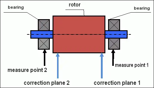
Fig. 3. Dynamic balancing diagram: to correct dynamic imbalance, correction weights are fitted in two planes and vibration sensors are mounted on both supports
Professional rotor balancing
We identify the type of imbalance and balance in one or two planes according to the rotor's design
Request the serviceQuick reference: identifying the type of imbalance
Use this table to quickly identify the likely type of imbalance and the number of correction planes required:
| Rotor geometry | L/D ratio | Likely type of imbalance | Correction planes | Equipment examples |
|---|---|---|---|---|
| Narrow disc | L/D < 0.25 | Static | 1 | Grinding wheels, thin pulleys, narrow impellers |
| Medium-width disc | 0.25 < L/D < 0.5 | Static + partly couple | 1-2 | Fan impellers, flywheels |
| Wide disc or short shaft | L/D ≈ 0.5-1.0 | Dynamic | 2 | Electric-motor rotors, wide impellers, pump rotors |
| Long shaft | L/D > 1.0 | Dynamic (couple predominates) | 2 | Cardan shafts, crusher shafts, mill rotors, long spindles |
Practical recommendations
Rigid and flexible rotors
An important addition to the classification is the distinction between rigid and flexible rotors:
- Rigid rotor: the working rotational speed is well below the first critical speed. The rotor barely deforms under centrifugal forces. For such rotors, balancing in two planes is sufficient. Most industrial rotors are rigid.
- Flexible rotor: it operates at a rotational speed close to, or above, the critical speed. The elastic bending of the shaft becomes comparable to the displacement of the centre of mass. Balancing flexible rotors requires special methods and may call for more than two correction planes.
When a preliminary mechanical check is needed
Before balancing, it is advisable to check:
- Radial runout: the rotor must not run out of true
- Axial runout: discs must be perpendicular to the axis
- The fit on the shaft: no misalignment when fitted
If geometric defects are found, they must be corrected first, otherwise balancing will be ineffective.
Rigid and flexible rotors: a critical distinction
One of the fundamental concepts in balancing is the division of rotors into rigid and flexible. This division determines both the very possibility of successful balancing and the methodology to use.
The rigid rotor
Definition: a rotor is considered rigid if its working rotational speed is well below its first critical speed and it does not undergo significant elastic deformation (bending) under centrifugal forces.
Characteristics:
- The working speed is usually less than 70% of the first critical speed
- Shaft bending under centrifugal forces is negligible
- Balancing in two correction planes is usually sufficient
- Instruments such as the Balanset-1A are designed precisely for working with rigid rotors
The flexible rotor
Definition: a rotor is considered flexible if it operates at a rotational speed close to, or above, one of its critical speeds. In that case the elastic bending of the shaft becomes comparable to the displacement of the centre of mass and itself contributes significantly to the overall vibration.
The problem: trying to balance a flexible rotor with the methodology for rigid rotors (in two planes) often ends in failure. Fitting correction weights may compensate for vibration at low, sub-resonant speed, but as the working speed is reached and the rotor bends, those same weights can amplify the vibration by exciting one of the bending mode shapes.
Important: this is one of the key reasons why balancing "does not work" even though every operation with the instrument has been carried out correctly. Before starting work, it is extremely important to classify the rotor by comparing its working speed with the known (or calculated) critical speeds.
How to identify the type of rotor
A practical method:
- Find out the rotor's working rotational speed (rpm)
- Carry out a coast-down test (measuring vibration as the rotor runs down after being switched off)
- If distinct peaks are visible on the run-down vibration graph, these are resonances (critical speeds)
- If the working speed is close to a resonant peak (±20%), the rotor is running in a danger zone
What to do when operating near resonance:
- If the resonance cannot be avoided (for example, the machine runs at a fixed speed that coincides with the resonance), it is advisable to change the mounting conditions of the unit temporarily during balancing
- For instance, reduce the stiffness of the supports or fit temporary resilient mounts to shift the resonance
- Once the rotor imbalance has been corrected and the vibration normalised, the machine can be returned to its standard mounting conditions
Conclusion
Correctly identifying the type of imbalance is the first step towards successful balancing. Knowing the rotor's geometry (the L/D ratio) lets you anticipate the dominant type of imbalance in advance and choose the optimal strategy.
Key takeaways:
- Narrow discs (L/D < 0.25) — static imbalance, one plane is enough
- Most industrial rotors (L/D > 0.5) — dynamic imbalance, two planes are required
- If single-plane balancing worsens the vibration at the other support, switch to two-plane balancing
- Always check the rotor's geometry before balancing
Modern two-channel instruments such as the Balanset-1A make it possible to perform both single-plane and two-plane balancing, automatically calculating the correction weights required.
Rotor balancing
Instruments and services for single-plane and two-plane balancing
The Balanset-1A instrument
A two-channel instrument for balancing rigid and flexible rotors
Buy the instrumentQuick checklist
- Measure the rotor's length-to-diameter (L/D) ratio
- Check radial and axial runout before balancing
- Verify the rotor's fit on the shaft
- Use one plane for narrow discs, two for L/D over 0.5
- Switch to two planes if the other support worsens
- Compare working speed against critical speed